
Multi-unit abutments, or MUAs, provide a standardized restorative interface between dental implants and a screw-retained prosthesis. In full-arch implant restorations, they help manage divergent implant positions, restorative height, screw-access direction, and the transition from surgery to prosthetic design.
For the dental laboratory, successful MUA cases depend on more than the abutments themselves. Component identification, scan accuracy, digital library matching, cross-arch verification, CAD design, and final quality control all need to work as one connected workflow.

What Multi-Unit Abutments Actually Do in a Full-Arch Restoration
A multi-unit abutment is a prefabricated prosthetic component placed between an implant fixture and a screw-retained restoration. Once the MUA is seated, the prosthesis is restored at the abutment level instead of connecting directly to the implant platform.
The restorative stack typically looks like this:
Implant fixture → Multi-unit abutment → Prosthetic interface or cylinder → Screw-retained full-arch prosthesis
This arrangement is especially useful when several implants have different angulations or vertical positions. The MUAs create a more consistent restorative platform across the arch, allowing the laboratory to design a common path for the framework and manage screw channels more predictably.
They can also move the restorative interface coronally, which influences tissue depth, emergence profile, hygiene access, and the geometry available for the prosthesis.
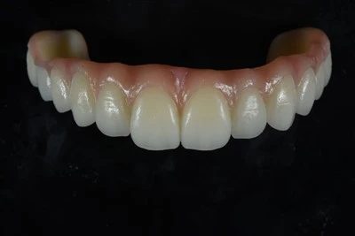
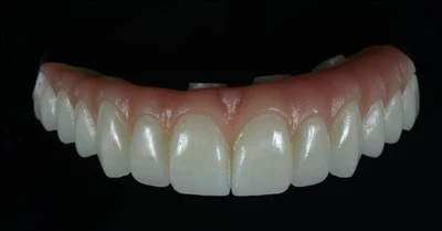
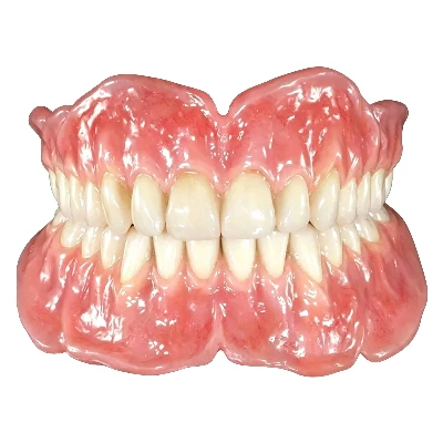
This is one reason MUAs are widely used in All-on-4, All-on-6, and other fixed implant-supported full-arch bridge restorations. They are also useful in shorter screw-retained implant bridges when implants are not sufficiently parallel.
One point matters from the beginning: MUAs make a passive-fitting prosthesis easier to design, but they do not create passive fit by themselves. The accuracy of the impression or scan, component identification, CAD data, fabrication process, and verification still determines how accurately the final bridge seats.
Selecting the MUA: Angulation, Cuff Height, and Restorative Space
MUA selection has a direct effect on everything the laboratory does afterward. Three variables deserve particular attention: angulation, cuff height, and available restorative space.
Straight vs. Angled Multi-Unit Abutments
Straight MUAs are generally used where implant trajectory already supports the intended restorative path. Angled MUAs redirect that path when implants are tilted or divergent.
Common configurations include:
|
MUA configuration |
Typical restorative purpose |
|
0° / straight |
Maintains an acceptable existing implant trajectory |
|
17° |
Moderate redirection of the restorative axis |
|
30° |
Greater correction for tilted implants |
|
45° or other angles |
Available in selected implant systems for more demanding trajectories |
Exact options depend on the implant manufacturer and component family. For a broader comparison of how prefabricated and individualized implant components differ, see this guide to custom and stock implant abutments.
This is particularly relevant in an All-on-4 configuration, where posterior implants are commonly tilted while anterior implants may be more axial. An angled MUA can redirect the prosthetic connection so the screw-access channel emerges in a more useful occlusal or palatal position. The same principle becomes directly relevant when designing an All-on-4 zirconia bridge.
From the laboratory perspective, the goal is not simply to make implant axes look parallel in CAD. The selected MUA must support the planned tooth position, framework thickness, screw-access location, and final prosthetic contour.
Cuff Height and Restorative Space
Cuff height determines where the restorative platform sits relative to the peri-implant soft tissue. If the platform is too deep, hygiene access and prosthetic contour can become difficult. Excessive height can also compromise emergence design or available prosthetic space.
The appropriate cuff height should therefore reflect the clinical soft-tissue depth and the specifications of the selected implant system.
Restorative space matters at the same stage. Some laboratory protocols use approximately 7–8 mm of vertical space for certain titanium-bar hybrid designs, while zirconia full-arch restorations may require around 10 mm or more, depending on the component geometry, framework design, and material system.
Those figures are useful planning references, not universal minimums. The actual requirement has to be checked against the prosthetic design and manufacturer recommendations.
Before CAD Design: What the Lab Must Confirm
A complete STL file does not automatically mean a full-arch case is ready for design.
Before the CAD technician starts, the laboratory should verify the component chain:
Physical implant/MUA → Scan body → Digital library → CAD restorative component
Each part of that chain needs to match.
At case intake, the laboratory should confirm:
- Implant manufacturer and implant line
- Platform or connection
- MUA manufacturer or component family
- MUA angle
- Cuff height
- Restorative level
- Scan body used
- Compatible analog or model component
- Correct CAD library
A mismatch at this stage can create a restoration that looks completely reasonable on screen while being based on the wrong interface geometry.
For example, if a posterior MUA scan body is assigned to the wrong digital library, the software may interpret its position or connection incorrectly. That error then carries into the framework before milling has even started.
This is why component verification should happen before detailed prosthetic design, especially when the clinic works with several implant systems.
A reliable implant laboratory should stop the case and clarify doubtful component information instead of designing around uncertain data.

Implant-Level vs. MUA-Level Scanning: What Changes for the Lab?
Full-arch digital records may be captured at implant level or at MUA level. These workflows are related, but the laboratory cannot treat them as interchangeable.
Implant-Level Workflow
In an implant-level workflow, the scan body connects directly to the implant. The laboratory receives the implant position and can then incorporate the planned abutment into the digital restorative workflow.
This can be useful when the final MUA selection has not yet been fixed or when virtual component planning is part of the case.
The laboratory still needs exact implant system and platform information to select the correct scan-body and component library.
MUA-Level Workflow
In an MUA-level workflow, the multi-unit abutments have already been seated and the scan bodies connect to those MUAs.
The laboratory is therefore designing from the established MUA restorative platform.
|
|
Implant-Level Scan |
MUA-Level Scan |
|
Scan body connects to |
Implant |
Multi-unit abutment |
|
MUA already finalized |
Not always |
Usually yes |
|
Main digital reference |
Implant interface |
MUA restorative interface |
|
Main advantage |
Greater component-planning flexibility |
More standardized restorative platform |
|
Common risk |
Incorrect virtual component selection |
Wrong MUA scan body or library |
The distinction should be documented clearly. Mixing implant-level and MUA-level information within the same case without proper identification can create serious component and design errors.
The lab also needs more than implant-position data. A complete full-arch record typically includes the upper and lower arches, bite or jaw-relation data, soft-tissue information, and, where useful, a scan of the provisional or previous prosthesis. For more detail on scan completeness and file quality, see what dental labs need from an intraoral scan.
Facial and smile photographs can also help when tooth position, lip support, smile line, or gingival display are important.
Photogrammetry may be incorporated into some full-arch workflows to capture the spatial relationship between implant or MUA positions. It is particularly relevant when cross-arch accuracy is a major concern.
Verifying Cross-Arch Accuracy Before Final Design
Full-arch accuracy deserves a separate verification stage because positional errors can accumulate across a long span.
With a single implant, a small positional discrepancy is relatively localized. In a full arch, several implant positions are connected through one rigid prosthesis. Small discrepancies in scan acquisition, impression transfer, model production, or component matching can therefore influence the seating of the entire framework.
A verification jig remains a common method for confirming that the laboratory model or digital record represents the intraoral MUA positions accurately. The jig is seated clinically before final framework fabrication and checked for complete, passive seating.
Modern workflows may also use photogrammetry, validated digital acquisition protocols, splinted impression techniques, or prototype-based verification.
The important principle is the verification itself.
Before committing an expensive final framework to production, the laboratory needs reasonable confidence that the cross-arch positional relationship is accurate.
This is also where the idea of passive fit should be handled carefully. MUAs help organize the restorative platform, but passive fit depends on the entire chain from data capture to fabrication. A perfectly selected MUA cannot compensate for incorrect positional data.
CAD Design: From Verified MUA Positions to a Full-Arch Prosthesis
Once the component information and implant positions are verified, CAD design can move from geometry to prosthetics.
The technician needs to consider the MUA positions together with tooth setup, available restorative space, framework geometry, screw-access channels, gingival architecture, emergence profile, occlusion, hygiene access, and any distal extension or cantilever requirements.
Screw-access position deserves early attention. A framework can be technically millable and still create an undesirable restoration if an access channel exits through a facial surface, incisal edge, or structurally weak area of the prosthesis.
MUA angulation helps manage this at the restorative level, while CAD design refines the final relationship between the screw channel and tooth position.
Hygiene also needs to be designed into the intaglio surface. Full-arch prostheses require adequate access for routine patient cleaning. Tissue contact, convexity, embrasures, and the transition between artificial gingiva and mucosa should therefore be evaluated as functional design features.
A full-arch prosthesis is successfully designed when it fits, functions, can be maintained, and can be manufactured predictably. The broader CAD/CAM dental workflow follows the same principle of validating data before moving from digital design into production.
For complex or highly esthetic cases, a PMMA prototype or provisional try-in can be valuable before final fabrication. It allows the clinic and laboratory to evaluate:
- Tooth position
- Smile and facial support
- Phonetics
- Vertical dimension
- Occlusion
- Screw-access locations
- Gingival contour and hygiene access
This step is particularly useful before transferring a finalized setup into a high-value zirconia restoration, including an All-on-X implant bridge.
Manufacturing and Final Lab QC
Once the design has been approved, the restoration moves into the appropriate manufacturing workflow.
Common MUA-based full-arch designs include a milled titanium framework with acrylic or composite teeth and gingiva, as well as zirconia full-arch prostheses connected through compatible titanium interfaces. Material selection depends on restorative space, prosthetic design, esthetic requirements, repair strategy, and the implant system being used.
The laboratory's work is not finished when milling is complete.
Final QC should cover the complete restorative system:
Fit → Components → Screw Access → Occlusion → Aesthetics → Documentation
The framework or prosthesis should seat completely on the model or verified analog positions. Component identity needs to be checked again, particularly when several similar restorative parts are used within the same implant family.
Screw-access channels should remain usable after staining, glazing, layering, or final contouring. Occlusal contacts and excursive relationships should be checked against the approved records. Gingival surfaces require appropriate finishing and polishing, and the final restoration should match the prescribed shade and tooth setup.
Torque values should always follow the manufacturer's current Instructions for Use (IFU) for the exact MUA and prosthetic screw being used. Values such as 15 Ncm or 35 Ncm appear in some component protocols, but they are not universal values for every MUA system.
Good quality control also keeps the case traceable. The laboratory should be able to identify the restoration, components, production stage, technicians involved, and final inspection status before shipment.

Common MUA Full-Arch Workflow Errors-and What to Send Your Lab
Most difficult full-arch cases do not become difficult because of one dramatic error. More often, a small information or component mismatch early in the workflow creates a larger problem later.
|
Common issue |
Possible consequence |
Lab response |
|
Wrong scan body or CAD library |
Incorrect digital component position |
Confirm implant/MUA system and rematch or request new records |
|
Implant-level and MUA-level files mixed |
Wrong restorative reference |
Clarify the restorative level before CAD |
|
Scan body incompletely captured |
Uncertain spatial position |
Request a corrected scan |
|
Incorrect or unconfirmed MUA angle |
Poor screw-access emergence |
Review component choice before final design |
|
Insufficient restorative space |
Thin or compromised framework |
Re-evaluate prosthetic architecture |
|
Missing bite or jaw relation |
Unreliable tooth setup and occlusion |
Obtain corrected records before fabrication |
|
Incomplete soft-tissue scan |
Poor gingival contour or hygiene design |
Request additional tissue data |
|
Cross-arch position not verified |
Framework seating problems |
Verify before final manufacturing |
A clear prescription prevents many of these delays.
For an MUA full-arch case, the laboratory should ideally receive:
- Implant manufacturer, system, connection, and platform
- MUA family, angle, and cuff height
- Exact scan-body information
- Upper and lower arch scans
- Bite or jaw-relation record
- Soft-tissue records
- Provisional or previous prosthesis scan when available
- Facial and smile photographs when esthetically relevant
- Requested restorative material and design
- Specific occlusal, gingival, or esthetic instructions
When a case is being transferred digitally to an external laboratory, having a consistent submission process also matters. This guide on how to send a digital dental case to a lab covers the broader file and communication requirements.
The best lab workflow also includes deliberate stop points. If the component system cannot be identified, a scan body is incomplete, the bite is inconsistent, or the available restorative space is clearly questionable, continuing directly into final CAD only moves the problem farther downstream.
Conclusion
Multi-unit abutments provide a practical restorative platform for full-arch implant prostheses, especially when implant angulation, tissue depth, and screw-access direction vary across the arch. Predictable results come from controlling the complete workflow: accurate component identification, correct restorative-level scanning, cross-arch verification, disciplined CAD design, appropriate manufacturing, and final QC.
ADS Dental Laboratory Ltd supports full-arch implant restorations through digital case receiving, implant component coordination, CAD/CAM design, prototype and final restoration production, and structured quality control. If you are planning an MUA-based full-arch case or looking for a long-term implant restoration outsourcing partner, contact our team to discuss your workflow and case requirements.